- History Home
- People, Leadership & Service
- A Legacy of Excellence
- History & Impact
- Meetings Through the Years
- Resources
Memoir - William R. Busing (1923 - 2016)Memoir | Publications | Curriculum Vitae | Awards | Videos | Slides | Articles | Obituary
Crystallographic Computing at Oak Ridge National Laboratory 1954 to 1968 William R. Busing ORNL Chemistry Division (retired), 317 Louisiana Avenue, Oak Ridge, Tennessee, 37830, USA. E-mail: [email protected]
The ORACLE (Oak Ridge Automatic Computer and Logical Engine)
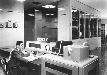
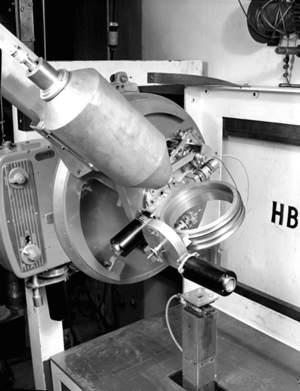
I arrived at Oak Ridge National Laboratory (ORNL) in September, 1954, and joined the neutron-crystallography group headed by Henri A. Levy. My previous work had been in Raman and infrared spectroscopy and I was interested in structures, but I had very little knowledge of crystallography. I was certainly aware of the pioneering work that had been done by Henri together with Selmer W. Peterson, who was on sabbatical for the year. I started out by trying to grow millimeter-sized crystals of various hydroxides. I knew that Henri had been learning to program for the ORACLE (Oak Ridge Automatic Computer and Logical Engine), and when I expressed some interest in this, he offered to teach me all about it while I waited for crystals to grow. According to Henri, the first step in writing a program is to make a flow chart, a procedure that I have found useful in all my subsequent work. We started out by writing a simple program to calculate Bragg angles and put out an ordered list. Shown in Figure 1 is the ORACLE, a vacuum-tube computer that occupied a large room. It had been built at Argonne National Laboratory by ORNL personnel and installed here during the previous year. Its cathode-ray-tube (CRT) memory consisted of 1024 40-bit words. Each word can be described as ten hexadecimal characters, using the symbols 0 to 9 and A to F. A word could be treated as one fixed-point number or as two five-character commands. Each command used two characters for the command and three for an address ranging from 000 to 3FF. Fixed-point additions and subtractions were done in a 41-bit accumulator, or A register, and multipli-cations and divisions used a 40-bit Q, or quotient register. Numbers in these registers could be shifted left or right, using either one or both registers. There were no index registers or indirect addressing. To step through a loop, we would set a counter initially and then increment it and test it on each pass through the loop. To step through an array, we would set an initial address in a command. Then after each pass we would pick it up, increment it, and put it back. Fig. 1. An engineer at the console of the Oak Ridge Automatic Computer and Logical Engine. Input and output were done with five-hole teletype tape. Four hole positions were used for the characters 0 to F and the fifth was a parity check Input tapes were prepared by typing on teletype machines, and output tapes were printed on these same machines. Programs were prepared in hexadecimal and temporary storage locations were assigned. If pi or other constants were needed, they would be manually converted to hexadecimal and included in the program. Then the program would be manually typed onto tape so that it could be loaded into the ORACLE, starting at a specified location. Input and output subroutines were available so that decimal data could be read by a program and output could be converted to decimal, punched, and later printed off line. At the console of the ORACLE was a cathode-ray tube that displayed the 32 x 32 grid representing one bit of the 40-bit words in the memory. One could follow the course of a program by watching where the spots brightened momentarily. A speaker also produced an audio signal as the commands were executed, and one could get to know what a particular program sounded like. Our Bragg-angle program was finally ready for its initial tests just before the December holidays. The program was loaded and started, but shortly thereafter the speaker started emitting a continuous tone and one area of the memory lit up brightly indicating that the program was in an unending loop. We followed the usual procedure of punching out and printing a dump of the memory contents. Overnight I found what I hoped was the single bug, and the next day I went back to get another shot at the ORACLE. But it was Christmas Eve, the mathematics party was in full swing, and the ORACLE was playing Christmas carols! I had to wait till after the holidays to get my first list of ordered Bragg angles. Absorption-correction software for the ORACLE The first crystals that I was able to grow were calcium hydroxide. The heavy-atom positions were known from the early x-ray work of Bernal and Megaw (1935), who also postulated the hydrogen positions. In previous neutron diffraction studies by Levy and Peterson the practice had been to grind the samples to a cylindrical shape, so that tabulated absorption corrections could be applied. This had been done by putting the oriented crystal on a sandblasting lathe and grinding the edges off. But calcium hydroxide is a layer structure that cleaves like mica, and the sandblaster immediately caused the crystals to open up like the pages of a book. This led Henri and me to consider whether we could use the ORACLE to calculate the absorption correction for a crystal whose shape had been carefully measured. In the first version of this absorption program, we integrated the correction over a few hundred equally-spaced scattering points within the crystal volume. Later a consultation with mathema-ticians showed us that we could get better accuracy by selecting the points and weighting the contributions according to the rules of Gaussian integration. This program (Busing & Levy, 1957) and a later Fortran version (Wehe, Busing, & Levy, 1962) were used for all our neutron-diffraction studies after that. Structure-factor data for fifty-three h0l reflections from calcium hydroxide were measured at two temperatures (Busing & Levy, 1957), and Henri suggested that we should make a Fourier projection. He had commissioned the ORNL Math Panel to prepare a Fourier program for us, but our first tries at using that program showed that it would be very tedious to use. This led us to prepare a new two-dimensional Fourier program more suitable for crystallographic purposes. This program initially calculated a look-up table with all the values of the sines and cosines that would be needed. Most of the rest of the memory was allocated to the map that would be produced. The indices and structure factor were read from paper tape one reflection at a time, and its contribution was added to each point of the map. After all the reflections had been included, an output table was punched so the map would be printed in a suitable format to be contoured by hand. Least-squares software written for the ORACLE To get more precise coordinates and interatomic distances, Henri suggested that we could use the method of least squares. My knowledge of least-squares refinement was based on Margenau and Murphy (1943). I was not even aware of the pioneering crystallographic least-squares refinement work of Hughes (1941). The parameters for calcium hydroxide included two coordinates, six anisotropic temperature-factor coefficients, and a scale factor, for a total of nine parameters. The ORACLE program that we wrote was probably designed for this particular problem. The appropriate derivatives were used to set up the full matrix, and a subroutine was available to solve the nine simultaneous equations. The four cycles of least-squares adjustments needed for convergence took about twenty minutes of ORACLE time. In order to calculate the standard errors of the distances and angles, we needed the variance-covariance matrix that could be derived from the inverse of the least-squares matrix; but no matrix inverter was available for the ORACLE at that time. Instead, we inverted the matrix by solving nine simultaneous equations a total of nine times, using as the nine column vectors (1,0,0,0,0,0,0,0,0), (0,1,0,0,0,0,0,0,0), etc. The nine solution vectors then formed the columns of the inverse matrix. At about this time Henri and I realized the desirability of writing a generalized least-squares program that could be used to adjust the parameters defining any arbitrary function. The function would be provided by the user, who would need only to write a subroutine to evaluate the function based on the parameters and the values of one or more independent variables for which experimental values had been obtained. For example, we refined the lattice parameters of diaspore (Busing & Levy, 1958) using observations of the Bragg angles from an x-ray powder pattern. Here the independent variables were the indices, along with an indicator as to whether the wavelength for an α1, an α2, or unresolved line should be used. A unique feature of this general least-squares program was that the user had the option of calculating the required derivatives of the function with respect to the parameters or letting the program calculate derivatives numerically. In the latter case the user would just provide a list of increments to be added to one parameter at a time. The function was recalculated with the incremented parameter, and the derivative was taken as the ratio of the change in the function to the parameter increment. This program and its successors (Busing & Levy, 1962) were so easy to use that other groups at ORNL and elsewhere used it routinely to analyze thermodynamic data, spectral patterns, and other complicated functions. Crystallographic least-squares refinement on the IBM 704 About 1958 an IBM 704 computer became available at the gaseous diffusion plant in Oak Ridge. Although this required a drive of about seven miles, the advantages over the ORACLE were considerable. These included a memory of 8,192 36-bit words, hardware floating-point arithmetic, index registers, removable magnetic tapes, and punched card input and output. An assembler was available to facilitate writing programs that would be automatically converted to binary form. Henri and I decided to write a least-squares program that could be used for the refinement of any crystal structure based on x-ray or neutron-diffraction data. Whenever we couldn't decide how to do something we left it as an option for the user. Thus the program could refine a structure based on either F or F2. An overall temperature factor or individual isotropic or anisotropic temperature factors could be used. Symmetry cards were included to allow for the refinement of any centrosymmetric or noncentrosymmetric structure. Atom multipliers were provided to correctly weight atoms in special positions or to treat disordered structures. Anomalous scattering factors could be included. Different scale factors could be applied to data from different samples. Henri and I wrote a program to invert a symmetric matrix in the space required to store only its unique upper-triangular elements (Busing & Levy, 1962). Although this program was later shown to be rather inefficient, it allowed for the adjustment of up to 120 parameters in the 8,192-word memory. When Carroll Johnson joined our group in 1962, he and Henri wrote an improved matrix inverter that made use of the Choleski method of factoring a symmetric matrix. We wanted to distribute this program to anyone who requested it. However, with instructions punched one per card, the source program consisted of over 4,000 cards. We considered that this would be too expensive to copy and ship. Instead, we distributed copies of the binary card decks that were produced by the assembler. A handbook was available that gave detailed instructions on how to use the program (Busing & Levy, 1959). In 1961 Kay Martin of the ORNL Math Panel joined our group to help with computer programming. Her first job was to convert the structure-factor least-squares program to Fortran (Busing, Martin, & Levy, 1962). This made it easier for us to distribute the source program either on punched cards or via magnetic tape. When the ORACLE was replaced by the Control Data 1604 and later by the IBM 360, the Fortran program was easily adapted to the new computers. Availability of the Fortran source code also allowed others to make changes in the program. Jim Ibers and Walter Hamilton of Brookhaven National Laboratory improved the form for input of the symmetry information. Methods of correcting for extinction were introduced. Carroll Johnson added the ability to refine more complicated forms of thermal motion. No further printed reports were written, but the instructions included with the distributed program were kept up to date. The latest version lists nine persons as contributing authors. In 1982 Current Contents listed the 1962 report as a Citation Classic that had been cited more than 3000 times (Busing, 1982). The primary purpose of most crystallographic investigations is to obtain detailed information about the chemical structures of the molecules or ions involved. After the lattice parameters, atomic coordinates, and temperature factor coefficients have been obtained, it is desirable to calculate bond distances, bond angles, torsion angles, and other quantities, some of which depend on the observed thermal motion. It certainly is useful to obtain the standard errors of the calculated quantities, and these can be calculated in a straightforward way from the variance-covariance matrix that is proportional to the inverse matrix of the normal equations. After completing the first version of our crystallographic least-squares program Henri and I proceeded to write a Fortran program to calculate some fifteen different kinds of functions together with their standard errors (Busing & Levy, 1959). The functions calculated included bond distances, bond angles, torsion angles, the difference between two bond distances or angles, the sum of several bond angles, and nine more functions involving thermal motion. The calculation of standard errors requires the values of the derivative of the function with respect to each parameter involved. A unique feature of this program is that, instead of deriving expressions for these derivatives, we decided to determine them numerically by adding an increment to a parameter, recalculating the function, and computing the derivative as the ratio of the change in the function to the parameter increment. This method produces a correct result, even when certain parameters are constrained by symmetry or for some other reason, provided that the constraint is reapplied each time a parameter is incremented. Provision was made for the user to write subroutines defining any new functions desired. Available for this purpose were subroutines for picking up atomic coordinates and temperature factor coefficients, manipulating matrices and vectors, and calculating angles. Other mathematical routines could also be used. This program was later modified by Kay Martin to conform to the Fortran version of the least-squares program (Busing, Martin, & Levy, 1964). It has been kept up to date with a few improvements and has been generally distributed on request together with the least-squares program. Three-circle neutron diffractometer control using paper tape Shown in Figure 2 is the three-circle neutron diffractometer that we installed in 1960 at the newly operational Oak Ridge Research Reactor. A crystal monochromator centered in a concrete shield reflected the neutrons to produce a vertical beam. A General Electric diffractometer was mounted on its side to support the appropriately counter-weighted neutron counter. Centered on this instrument was a ring to provide the chi-angle orientation and support the phi-angle drive.
Fig. 2. The three-circle paper-tape controlled neutron diffractometer at the This instrument was controlled by electronics that read the desired angles two-theta, chi, and phi from paper tape. Motors would drive each shaft until the encoders registered the desired angles. It was arranged that the final adjustment of each angle would always be made slowly in the same direction to avoid backlash problems. With this then-new type of instrument we no longer needed to orient a crystal sample. We only had to center it and determine its orientation by observing the angles for two or more reflections. ORACLE programs were written to use this angle information to refine the orientation and prepare a tape with the angles for data collection. The methods we used for determining orientation and calculating diffractometer angles have been described (Busing & Levy, 1967). It was arranged that after the electronics had set the initial angles it would make a theta-two-theta step scan through the reflection, punching the observed counts on an output paper tape. This tape was then carried back to the ORACLE for further data processing to obtain the integrated count and the peak position in two-theta. Assuming that the counter has a large aperture, this peak maximum occurs when the reflecting plane best satisfies the Bragg condition. Deviations from the calculated two-theta were then used to further refine the orientation and lattice parameters. After the ORACLE was replaced by the Control Data 1604 computer the three-circle data collection programs were rewritten for that machine. The Control Data 160A auxiliary computer was used to convert from magnetic tape to paper tape and vice-versa. Four-circle x-ray diffractometer control using a DEC PDP-5 In the fall of 1962 I went to England to spend a year on sabbatical working with Owen S. Mills at the University of Manchester. There the computer engineers were in the process of installing the Ferranti Atlas supercomputer, a state-of-the-art machine that was to run several programs at a time, switching them in and out of memory from an auxiliary storage drum. Owen was having a four-circle x-ray diffractometer built by Hilger-Watts, and he intended to use the Atlas computer to control this instrument. Working in this time-sharing mode, the diffractometer would use only a small fraction of the computer's resources. I wrote computer programs to calculate instrument angles, drive motors, center reflections, calculate orientation, and collect intensity data. All these programs were written without the presence of the diffractometer that was not delivered until April of 1963. After the diffractometer was interfaced to the computer, we were only permitted to test it on Saturday mornings, times set aside for computer maintenance. After we got started it seemed as though the Atlas would never run for more than about fifteen minutes before it crashed. Then we would spend the rest of the morning arguing with the engineers as to whether the problem was with our software or with the computer hardware. I had to leave Manchester before these problems were solved. When I returned to Oak Ridge we wanted to install an automatic four-circle x-ray diffractometer, but I was sure that we didn't want to interface it to a large time-sharing computer. Cole, Okaya, & Chambers (1963) had recently described a diffractometer controlled by a dedicated IBM 1620 computer, but that computer, at about $100,000, was too expensive for our budget. Then we learned of the DEC PDP-5 computer that was available for about $20,000. We also knew that Tom Furnas of the Picker X-ray Corporation had recently designed and built a four-circle diffractometer that Picker intended to market for use with paper-tape control. It didn't take long for us to realize that we could easily control this diffractometer with the PDP-5 computer. In 1965 we produced the system shown in Figure 3. (Busing, Ellison, Levy, King, & Roseberry, 1968).
Fig. 3. a) The four-circle Picker x-ray diffractometer and the PDP-5 computer that was programmed to control it and b) Henri Levy at the keyboard of this instrument. (Photographs courtesy of ORNL). (Editor's note: Apparently this was the first computer-automated four-circle single crystal X-ray diffractometer; see the news article here.) The PDP-5 (a predecessor of the PDP-8) had a core memory of 4096 12-bit words divided into 32 pages of 128 words each. An instruction occupied one word and the type of instruction was defined by the first three bits so there were only eight different kinds of commands. Six of these instructions used seven bits to define an address that could be either on the same page or on page zero, but it could also refer to any location in the memory by indirect addressing. Hardware arithmetic was limited to addition, but a complete package of subroutines to perform floating-point arithmetic was available. Input or output was accomplished by a teletype interfaced directly to the computer. Input could be typed or loaded from punched-paper tape. Output could be printed or punched on tape. We decided to use Slo-Syn stepping motors that took one hundred steps to make a revolution. The angles of the Picker diffractometer were geared to change one degree for each turn of a drive shaft. Thus, with a motor on each shaft, the angles two-theta, omega, chi, and phi could be set to the nearest 0.01 degree without the use of encoders. To provide a check on the angles ORNL engineers designed an optical detector to signal the computer at each even degree. A feature of the PDP-5 that was new to us was the availability of a hardware interrupt. Thus any external action, such as the typing of a teletype key or the closing of a limit switch, could interrupt the program that was operating and jump to a special interrupt program. We knew that the Slo-Syn motors could run smoothly at 300 pulses per second, so we arranged for a crystal-controlled oscillator to interrupt the computer 300 times each second. An interrupt program would check to see which motors should be running and send a single pulse to step that motor forward or backward. Every 30th clock interrupt was treated as a tenth-of-a-second interrupt and used for timing counts or any required delays. At about the time the PDP-5 was delivered, Sharron King of the ORNL Mathematics Division joined our group to help with the diffractometer programming. Although an assembler program was available for the PDP-5, we found it useful to create an assembler program, written in Fortran, to run on the CDC 1604 and 160A computers. We put our instructions on punched cards, and the assembler produced a binary tape that could be loaded into the PDP-5. The subroutines for floating point arithmetic, trigonometric functions, and matrix operations took up about half of the memory. The other half would be loaded with programs for the particular operations we were performing. A setup program would be used to search for reflections, center them, and establish initial lattice parameters and sample orientation. Then a least-squares program could be loaded to refine this information. Finally, a data collection program would measure the reflections systematically, making step scans and punching the results on paper tape. This output tape would be processed further by the CDC computers. This data collection system remained in operation for almost twenty years. When it was acquired, the PDP-5 was one of the first minicomputers at ORNL. When it was finally decommissioned it was the oldest computer at the laboratory. This has been the story of one group's experiences in the early uses of computers for crystallography. Everything seemed new and exciting at the time we were working on it. We certainly never envisioned the days when similar things could be done on a laptop computer at unimagined speeds. But that seems to be the way science works.
References Bernal, J. D. & Megaw, H. D. (1935). Proc. Roy. Soc. (London) A151, 384. Busing, W. R. & Levy, H. A. (1957). Acta Cryst. 10, 180-182. Busing, W. R. & Levy, H. A. (1957). J. Chem. Phys. 26, 563-568. Busing, W. R. & Levy, H. A. (1958). Acta Cryst. 11, 798-803. Busing, W. R. & Levy, H. A. (1959). ORNL-CF-59-4-37, A Crystallographic Least-Squares Refinement Program for the IBM 704. Busing, W. R. & Levy, H. A. (1959). ORNL-CF-59-12-3, A Crystallographic Function and Error Program for the IBM 704. Busing, W. R. & Levy, H. A. (1962). Comm. Assoc. Comp. Mach. 5, 445-446. Busing, W. R. & Levy, H. A. (1962). ORNL-TM-271, OR GLS, A General Fortran Least Squares Program. Busing, W. R. & Levy, H. A. (1967). Acta Cryst. 22, 457-464 Busing, W. R., Martin, K. O., & Levy, H. A. (1962). ORNL-TM-305, OR FLS, A Fortran Crystallographic Least-Squares Program. Busing, W. R., Martin, K. O., & Levy, H. A. (1964). ORNL-TM-306, OR FFE, A Fortran Crystallographic Function and Error Program. Busing, W. R., Ellison, R. D., Levy, H. A., King, S. P., & Roseberry, R. T. (1968). ORNL-4143, The Oak Ridge Computer-Controlled X-ray Diffractometer. Busing, W. R. (1982).Current Contents, 13, 20. Cole, H., Okaya, Y., & Chambers, F. W. (1963). Rev. Sci. Inst. 34, 872-876. Hughes, E. W. (1941).J. Am. Chem. Soc. 63, 1737-1752. Margenau, H. & Murphy, G. M. (1943). The Mathematics of Physics and Chemistry. New York: Van Nostrand. Wehe, D. J., Busing, W. R., & Levy, H. A. (1962). ORNL-TM-229, OR ABS, A Fortran Program for Calculating Single-Crystal Absorption Corrections. |